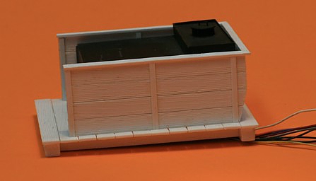
The photo below shows the third tender out of a total of three that I built. I am planning to use this tender and scrap the others.
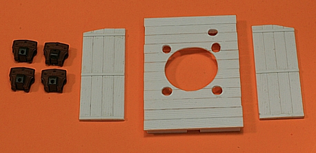
The only reason that I decided to build a tender for my Porter was to be able to accommodate a 1.1 cubic inch enclosure for the loco’s QSI "Hi-bass" loudspeaker and also a dummy water tank to hide the SoundTraxx Micro-Tsunami DCC decoder. The Tsunami model that I chose was the TSU-750 DCC decoder model #826001 (light steam). It just fits inside the water tank that's located at the back of the tender.
There will be a total of 7 wires that will travel under the tender and loco and these will be for the track voltage (2), motor (2), headlight (2) and the sound cam wiper (1). The loudspeaker will connect inside the tender. Since "Fido" didn't have a backup lamp, I decided that my tender wouldn't have one either.
The manufacturer of the loudspeaker (QSI) recommended that particular cubic inch capacity and the resulting sound is incredible.
Now I turned my attention toward sound control. The photograph below shows the under side of the loco. The GME sound cam which will control the "chuff's" from the loco is located on the front axle (right-hand side of photo) and a small piece of fibre glass PCB is glued with 2-part epoxy to the cover in order to provide a stable platform for me to solder the connecting wires and the wipers. Note the rectangular cutout in the gear box cover. This provides the necessary clearance for the cam to rotate and also allows the wipers to touch the cam and detect a momentary "circuit closure" 4 times for every revolution of the drivers and thus in perfect synchronization with the pistons and connecting rods. I found the folks at GME (in particular, Randy Lee) to be very helpful and the advice that I received was priceless.

It was at this point that I temporarily connected the Tsunami decoder in the tender to the loco and tested everything. It was 100% successful.
In the past, I have tried to use DCC sound systems without a synchronization cam and found that either the loco would start to move without the exhaust chuff sound or it would start "chuffing" before the loco was moving. Very unrealistic indeed. Based on my experience, a synchronization cam is well worth the trouble and additional time of installation.
Locating the DCC decoder in the tender has a major drawback compared to a boiler mounted system. Boiler mounted systems have less wires travelling between the tender and the locomotive - I have seven wires. One option that I could have taken was to have mounted the Micro-Tsunami under the cab roof but then there's the problem of hiding the wires and where would the QSI Hi-bass speaker go? When working with a small locomotive such as the Porter, it's all about making the right compromises remember, even in O-scale, this Porter is smaller than an average HO-scale loco.
Click on the arrow below to see the links for the remainder of this construction project or here to see part 4.

